Chassis Tuning
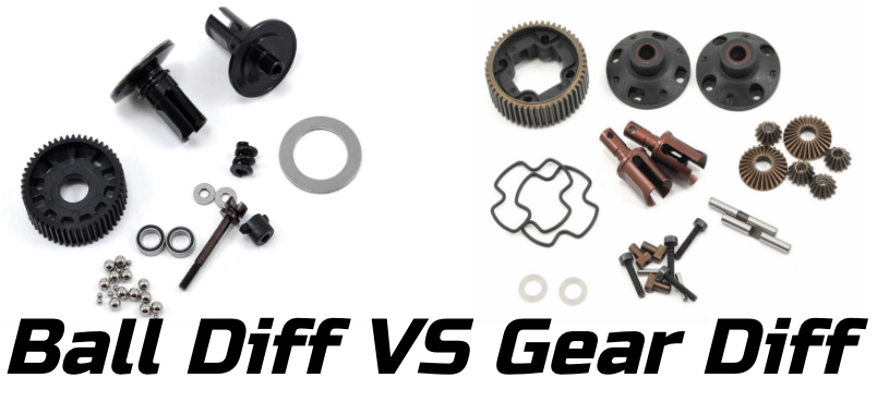
Ball VS Gear Differentials
Roll Centers and Moments
There is a balancing act that very few realize is happening with suspension geometry. Camber gain is the primary motivator when looking at initial pivot (hinge or ball stud) locations when designing a car. However, since most cars are designed properly with camber gain being pretty close no matter what holes you choose, everyone focuses on the roll center created by those pivot locations.
Here is a geometry review when it comes to roll centers:
You can simplify a suspension to singular points that forces are applied at. For this example assume the car is in the middle of the corner with no throttle or brakes being applied and we are looking at an outside tire.
Picture 1:
There is a chain of forces at work – the tire against the ground, the tire against the hub, the hub against the links, and the links against the chassis.
The force of the ground against the tire is pushing in, but since it’s pushing below the arm, a torque (or moment) is created. To prevent the hub from rotating clockwise, the upper link is in tension countering the hubs rotation. This gives us two forces pushing to the left on the hub. Thus the a-arm is in compression pushing to the right against the tire.

Looking at a simplified version, the arm is pushing on the chassis and the upper link is pulling on it. This is trying to roll the chassis.

You can then change how the forces are acting on the chassis and at what angle. Changing the angle would be like raising or lowering one end of the turnbuckle.

Changing the height at both ends changes the location of the force as well as the magnitude. Remember, torque is a function of force AND distance, so if you have a longer distance you can get away with less force to achieve the same torque. Raising both links reduces the force needed to counteract the torque the tire is placing on the rim/hub. This means there are lower forces in the upper and lower link, but the moment arms are now longer as well. Its a two-for-one sale.

This is also why you need the upper link locations, lower link locations, and tire contact patch to calculate the roll center. The roll center is the easy way to understand how the forces exerted on the tire are being applied to the chassis.
The distance between the roll center and the COG is yet another layer in the cake that is suspension geometry. It’s really hard to have it and eat it, too!
I completely ignored the COG when looking at the forces above to keep it simple, but it plays a huge role (HA!). Imagine applying a torque to a broom. You hold it vertically and grab the broom in the middle (at the COG) and rotate it. It rotates easily without much resistance. Now grab the broom at the bottom (below the COG) and rotate it. Now the broom willingly keels over. Now grab the broom at the top of the handle (above the COG). The broom actually resists rolling. Where ever you grabbed the broom is like the roll center and how it interacts with the chassis and center of gravity.