Tech Tips and Insight
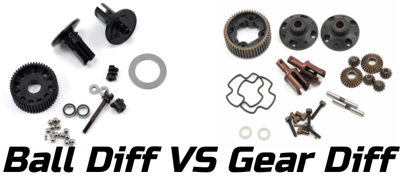
Ball VS Gear Differentials
More MAh, More Power. The race to increase capacity.
Example as to why a higher capacity pack will give more current:
Going with a 3000 mah 10c and 6000 mah 10c as example packs and assuming at 10mph the resistance (and impedance) of the electrical system is .1 Ohms and the back emf is averaging 4 volts.
With this setup and assuming a pack voltage of 8 volts (almost full and an even number to work with), the system will pull 40 amps if this voltage is maintained. The math I’m using for that is very simplified for what the whole system is, but it is close enough for this discussion:
Delta(V) = IR
VBattery – Vmotor = I(0.1ohms)
8volts – 4 volts = I(0.1ohms)
4volts/0.1ohms = 40 amps
This is higher than the 3000 mah pack can safely give, so the demand for current pulls it’s voltage down to 7 volts. At this point the equation works out to 30 amps:
7volts – 4volts = I(.1ohms)
3volts = I(0.1ohms)
3volts/0.1ohms = 30 amps
30 amps x 7 volts gives you 210 watts.
Same idea, but with the 6000 mah pack. The setup wants 40 amps. The voltage will dip a touch under load, but not as much as the smaller pack. This is a function of the packs internal voltage, but to make it easy lets just say it drops to 7.5volts.
7.5volts – 4volts = I(0.1ohm)
3.5volts/(0.1ohms) = 35 amps
35 amps x 7.5 volts = 262.5 watts
That’s 25% more power!
Obviously no one is running packs only capable of 30 amps, but the idea still applies. It’s just a diminishing point of return as the voltage drop under load becomes smaller and smaller with each capacity or C rating increase. The biggest arguments about packs are centered around this… sure you can buy those amazing new cells that just came out for $100, but what percentage of power are you gaining over a “sportsman” pack for $60? What about even cheaper packs straight from asia? With no standards when it comes to labeling how a pack will perform (short term as well as long term) it all comes down to the arguments you see every other week on various forums about the pack of the week and personal experience.
As always, that last 10% of performance costs as much as the initial 90%.
The voltage will always drop for batteries under load. When we say the battery should be able to deliver, we mean that it won’t drop to 6 volts while providing “X” amount of current. Here’s another example to help clear it up:
For this example, I’m simplifying the “C” rating to the idea that the 6000 mah 10C pack can deliver 60 amps continuous before it drops below 6 volts. This doesn’t mean that when it’s fully charged it will supply 60 amps at 8.4 volts and then all of a sudden drop to 6 volts when you try to pull 61 amps. The voltage drops roughly proportional to the percentage of power demanded from it. If you demand 30 amps, a full pack will probably be around 7.5 volts. If you demand 50, it will probably be close to 6.5 volts. 60 amps will put it right at 6 volts. If you remove any current demands, the pack will jump back up close to 8.4 volts.
The “drops quickly, levels out, and then dumps” voltage curves you are thinking of are for constant current discharge rates. You take a pack, discharge it and plot the voltage. This just tells you how the pack will react under constant currents, not varying ones. If you discharge one pack at 30 amps and another at 60, the voltage curve for the 60 amp run will always be below the 30 amp run when plotting it not only against time, but against how many mah have been discharged.
Voltage dips that you see from in car telemetry devices or other on track recording systems are caused by high current demands at low rpm. The voltage quickly recovers primarily because the demand diminishes as the rpm of the motor increases. At low rpm there is very little impedance and the back emf is also very low. This creates a high delta voltage and a very low overall resistance, so high current spikes and battery voltage drops are the result.
Roll Centers and Moments
There is a balancing act that very few realize is happening with suspension geometry. Camber gain is the primary motivator when looking at initial pivot (hinge or ball stud) locations when designing a car. However, since most cars are designed properly with camber gain being pretty close no matter what holes you choose, everyone focuses on the roll center created by those pivot locations.
Here is a geometry review when it comes to roll centers:
You can simplify a suspension to singular points that forces are applied at. For this example assume the car is in the middle of the corner with no throttle or brakes being applied and we are looking at an outside tire.
Picture 1:
There is a chain of forces at work – the tire against the ground, the tire against the hub, the hub against the links, and the links against the chassis.
The force of the ground against the tire is pushing in, but since it’s pushing below the arm, a torque (or moment) is created. To prevent the hub from rotating clockwise, the upper link is in tension countering the hubs rotation. This gives us two forces pushing to the left on the hub. Thus the a-arm is in compression pushing to the right against the tire.

Looking at a simplified version, the arm is pushing on the chassis and the upper link is pulling on it. This is trying to roll the chassis.

You can then change how the forces are acting on the chassis and at what angle. Changing the angle would be like raising or lowering one end of the turnbuckle.

Changing the height at both ends changes the location of the force as well as the magnitude. Remember, torque is a function of force AND distance, so if you have a longer distance you can get away with less force to achieve the same torque. Raising both links reduces the force needed to counteract the torque the tire is placing on the rim/hub. This means there are lower forces in the upper and lower link, but the moment arms are now longer as well. Its a two-for-one sale.

This is also why you need the upper link locations, lower link locations, and tire contact patch to calculate the roll center. The roll center is the easy way to understand how the forces exerted on the tire are being applied to the chassis.
The distance between the roll center and the COG is yet another layer in the cake that is suspension geometry. It’s really hard to have it and eat it, too!
I completely ignored the COG when looking at the forces above to keep it simple, but it plays a huge role (HA!). Imagine applying a torque to a broom. You hold it vertically and grab the broom in the middle (at the COG) and rotate it. It rotates easily without much resistance. Now grab the broom at the bottom (below the COG) and rotate it. Now the broom willingly keels over. Now grab the broom at the top of the handle (above the COG). The broom actually resists rolling. Where ever you grabbed the broom is like the roll center and how it interacts with the chassis and center of gravity.
The Tekin Current Limiter Function
Current limiter does just what it sounds like; limits the current going to the motor. However, how the esc actually does this and why you should use it sometimes isn’t so clear.
To understand how it works, we first need to understand what the point is. Limiting the current would be like setting the slipper looser. Allowing more current to flow to the motor is like tightening the slipper. More current = more torque in the same way a tight slipper will allow more torque through than a loose slipper. The key idea to take away from this is that neither one limits the top end of the car. A loose slipper will take a long time to top out on a drag strip, but it will get there eventually. The same goes for the Current Limiter. It limits acceleration potential, not top speed. However, it is much better (more efficient and less wear and tear on the drivetrain) to electronically limit the torque than to set the slipper loose. The slipper should be set just to absorb impacts from landing, not normal acceleration.
The current limiter can be set from 0 to 100 in Hotwire. 100 means the esc doesn’t think about the current going to the motor: whatever the motor wants it gets. Setting the current limiter to anything other than 100 reduces the maximum current allowed to the motor. The feel of this number is rather arbitrary, depending on your motor, gearing, vehicle weight, etc. People with like setups can trade current limiter values easily, but you will probably need to determine what current setting will be best for you on your own time. 80 is a typical number for mod motors that curbs harsh acceleration around 0 rpm or spikes caused from landing on power. 60 starts to really mellow out the torque output of a mod motor making for an easy to drive car in slick conditions. On the other hand, 60 might not even be noticeable with a stock motor. The best thing to do is go down 20 at a time until you notice a difference, then go up or down 10 for rough tuning, and finally 5 at a time to fine tune to a particular track.
HOW the esc does this is pretty straight forward. It measures the current passing through and if it approaches the artificial ceiling you’ve selected it will cut back on the throttle. Let’s say at 0 rpm your motor will draw 100 amps and at 10,000 rpm your motor now draws very little (0 for arguments sake). 100 amps at 0 rpm is full torque, but if we set the current limiter to 80 (and again assume with this motor it’s a straight forward 80%) while grabbing full throttle at 0 rpm, the esc backs off the throttle until only 80 amps are flowing through. As the motors demand for current drops off as it approaches 10,000 rpm, it’s safe to say that at about 2,000 rpm (20% of max) the motor can only draw 80 amps max. At this point the esc is back to providing full throttle having reduced the torque at takeoff allowing for a smooth start to your a-main.
Typical reasons for using the current limiter are preventing wheel spin on slick tracks, cooler running electronics by reducing power going through the system, smoothing out “nitro finger” for those coming from the piston packing side, or safeguarding against pulling to hard on the trigger when someone takes them out and the adrenaline starts flowing.